
Echo Bender

A year ago I built a effect pedal based on the Echo Bender by Casper Electronics. The schematic can be found here and an Instructable of an Echo Bender clone can be found here. On those sites you can also find videos to get an idea on how the Echo Bender sounds. First I built the whole pedal based on the schematic from above on a breadboard to see how and if it works.
Then I designed a strip-board as following and soldered everything together: 

Today, after one year, I finally found some time and some “trash” to build the housing. The housing basically consists of an old case for a film roll and three cork bungs.


DIY Longboard
This post doesn’t really have anything to do with media, but as I was recently asked by a lot of people on how I built my Longboards I decided to upload a small list of pictures and instructions. This isn’t a proper Tutorial but it should give you an idea where to start if you want to build your own Longboard.
The Setup:
Paris Trucks 180mm
Flashbacks 70mm 78A
SUNRISE Bearing + Spacer

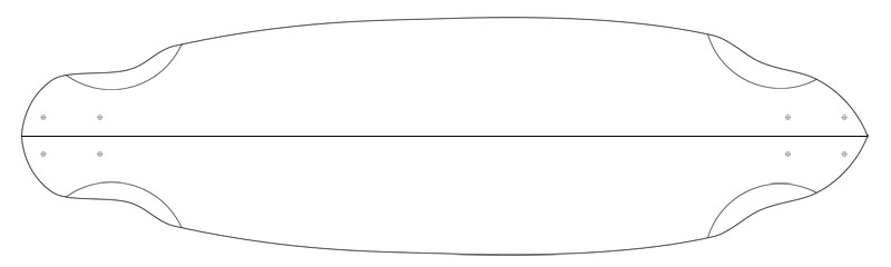
The Shape:
Wheelbase: 77cm
Length: 95cm
Width: 26cm
Concave: 1,3cm
The Press:
Made from an old table I sawed in half. Then I drilled some holes for the threaded rods, which then press both table halves together. Pretty basic and for free, but effective.

Structure:
Aluminium oxide (FEPA 40)
Bidiagonal-Glass-Fabric Glasgelege (320g/m²)
Birch Plywood (4mm)
Birch Plywood (4mm)
Unidirectional-Glass-Fabric (440g/m²)
Bidiagonal-Glass-Fabric (320g/m²)
Step 1:
Print the shape (5x A4), glue all pieces together and cut out the shape.


Step 2:
Cut the plywood into two 100cm * 30cm pieces, glue them together with around 50g of thickened epoxy resin and put them in the press.


Step 3:
Take it out of the press, be impressed how nice the concave is and colour it red with wood stain.


Step 4:
Cut the bidiagonal glass fabrics into 100cm x 30cm pieces and laminate one of them on the top of the deck with around 100g of epoxy resin.


Step 5:
Draw the shape on the bottom side of the deck, and then laminate the unidirectional and bidiagonal glass fabrics on the bottom with around 220g of epoxy resin. I also added some pics.


Step 6:
Cut out the Shape with a jigsaw and drill some wholes for the trucks. Also sandpaper the edges.

Step 7:
On the top I put a little graphic as well as some aluminium oxide which functions as a grip-tape.


Step 8:
Install setup and go cruising.


And here are some more pictures from another one I build. As I was new to Barcelona I used the map of Barcelona as the deck design, so I couldn’t get lost.


Time-lapse Dolly
 As one of my hobbies is photography I always wanted to play around with a time-lapse dolly. Unfortunately they are quite pricey. When I salvaged an step motor from some old scanner, I knew immediately that this is going to be a nice time-lapse dolly project. The first Idea was to use the motor as an engine for a small “wagon” where the camera is placed on. However, as I did not have much time to build some proper wagon I decided for an easier approach. In this approach the stepper is on a fixed position and is attached to a wagon with a string. The string is coiled up by the stepper and therefore shortens the string which pulls the wagon to the stepper.
To control the stepper I used the Teensy 2.0 micro controller and the L298N dual full-bridge motor driver. I added two potentiometer to the micro controller with whom I can set the interval and the distance the stepper should pull the wagon. The strip-board can be seen below: The eight diodes (Schottky Barrier Rectifier) protect the micro-controller from counter-electromotive force produced by the stepper. Unfortunately there are some flaws with this circuit. For instance should the micro-controller be powered by an independent power supply from the power supply who powers the stepper. This circuit as it is now could harm the micro-controller. Of course I tried the circuit first on a breadboard before soldering everything together.

Then I put everything on a piece of wood and the system was ready to go: For testing I used a GoPro Hero2 camera which is perfect for testing as it is really lightweight and has also a built-in time-lapse mode. In the first test I just attached the GoPro to an skateboard, which was pulled by the stepper over the terrace.
It turned out that the joints between the tiles were rather deep for the skateboard wheels, which resulted in a really shaky inconstant video. So in the next test I built a LEGO wagon for the GoPro. I placed the LEGO wagon in some kind of guide rail, which kept the wagon on track. Here is the Video, without any post-processing (Image Stabilization):
We can see that the footage is still rather shaky and the speed is not really constant. This is mainly because the wheels of the wagon were not perfectly round. Furthermore was the used string a little bit elastic, which caused that through some intervals the string just built up some tension and did not move the wagon. In the next step this tension was released and the wagon was pulled further than supposed.
